To begin the electric conversion the rear sprocket needed to be redesigned. The gear ratio was calculated based on the electric motor's specifications and the bike+rider's weight. A new 55 tooth sprocket was designed in SolidWorks and sent to SprocketSpecialists to be machined. The projected top speed with the new gear ratio is 95 mph. What's more impressive is the torque, which will top out at roughly 280 Nm depending on final battery specs. This brings the bike into drag racing territory, with most Pro Stock bikes making torque in the 270 to 550 Nm range.
The original 36 tooth sprocket.
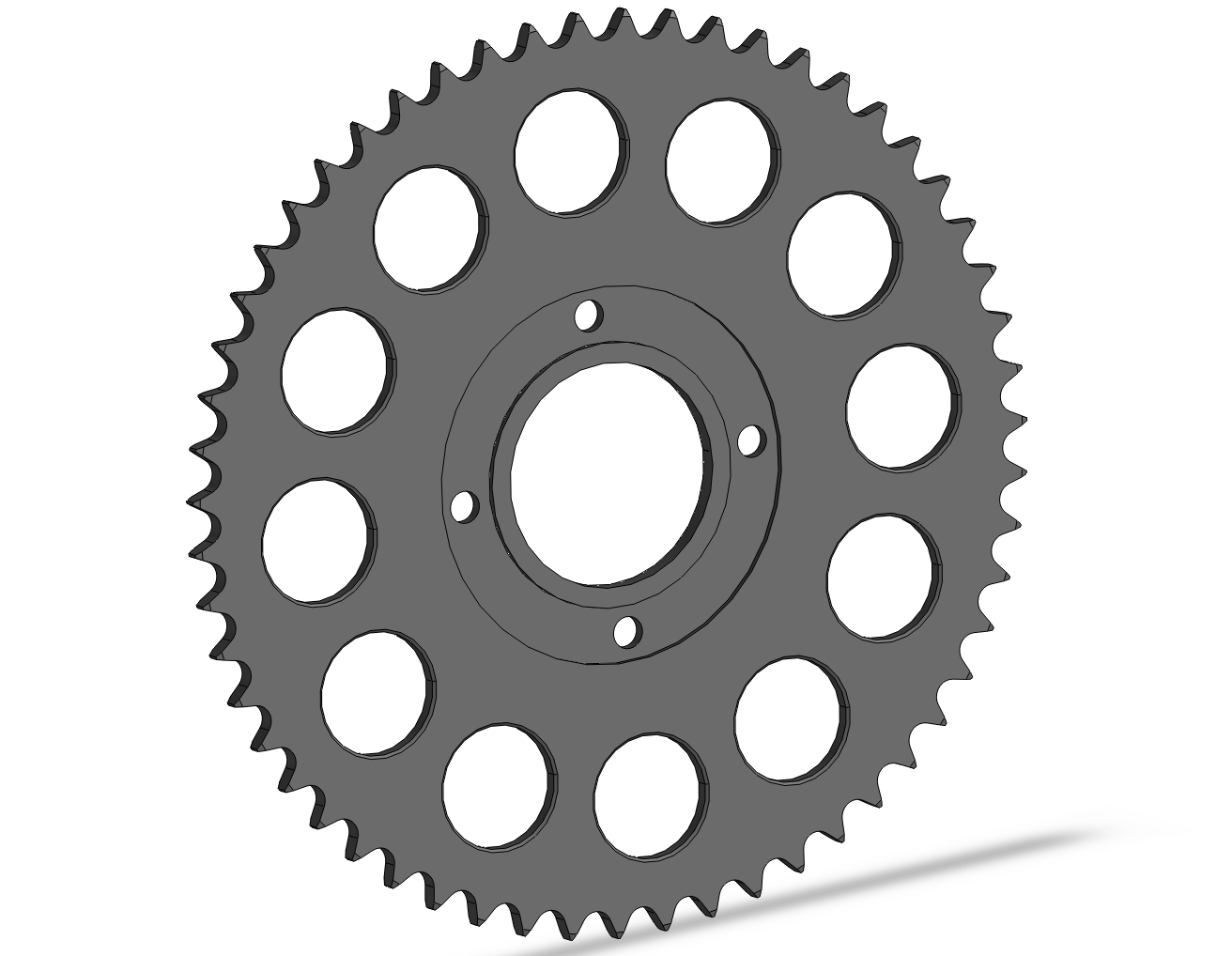
New Sprocket Design
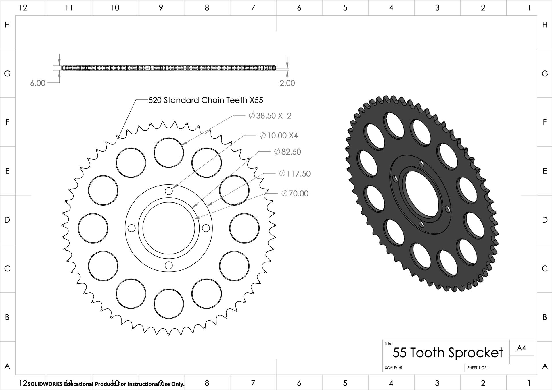
SolidWorks model and drawing for the new sprocket
Using the peak torque rating of the e motor as the external force, a quick simulation was run in SolidWorks with a factor of safety of 1.5. It can be inferred from the study that this sprocket will be strong enough for a prototype part, being displaced by only 0.111mm in the weakest areas in extreme conditions. Looking at the stress simulation, there are four small stress concentrations around the mounting holes. This means that the sprocket is expected to plastically deform here under peak loads and need some supporting features in future iterations.
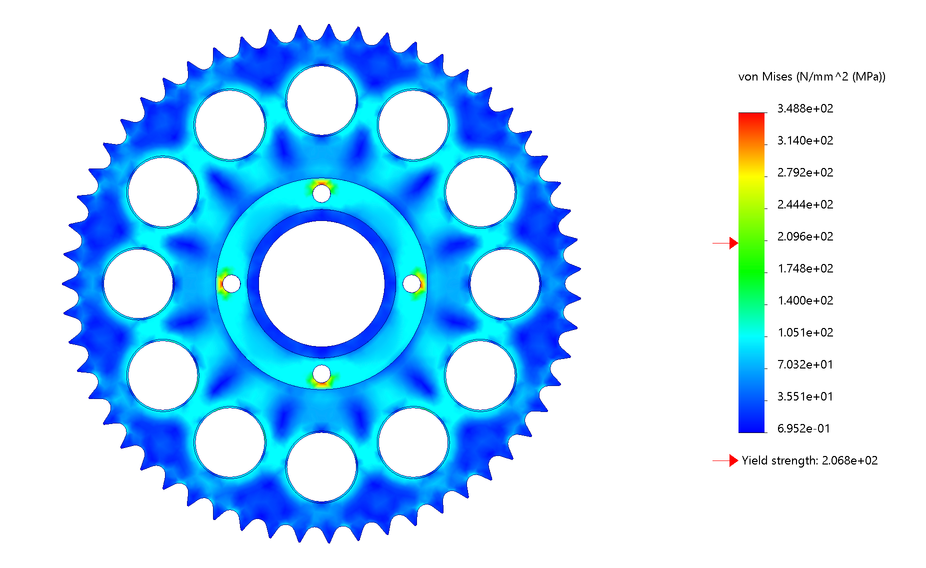
Stress Simulation
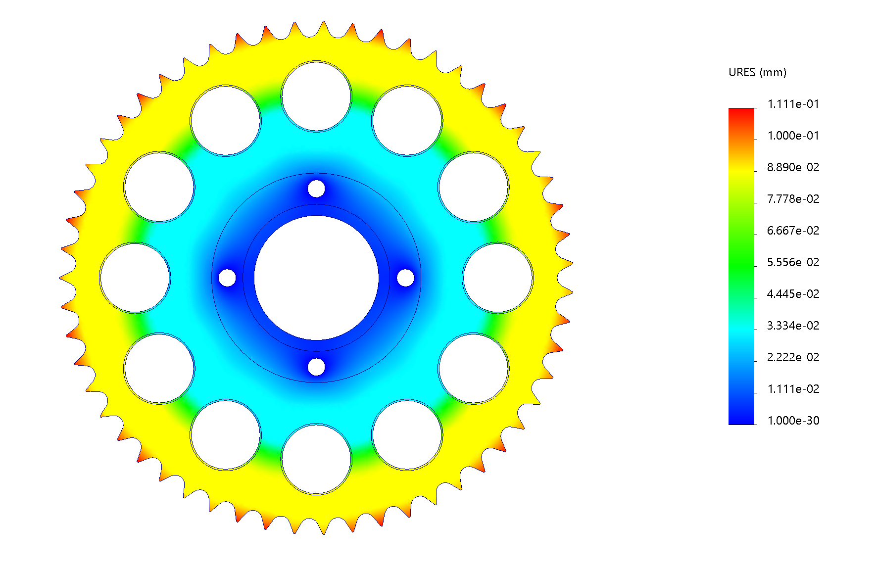
Displacement Simulation
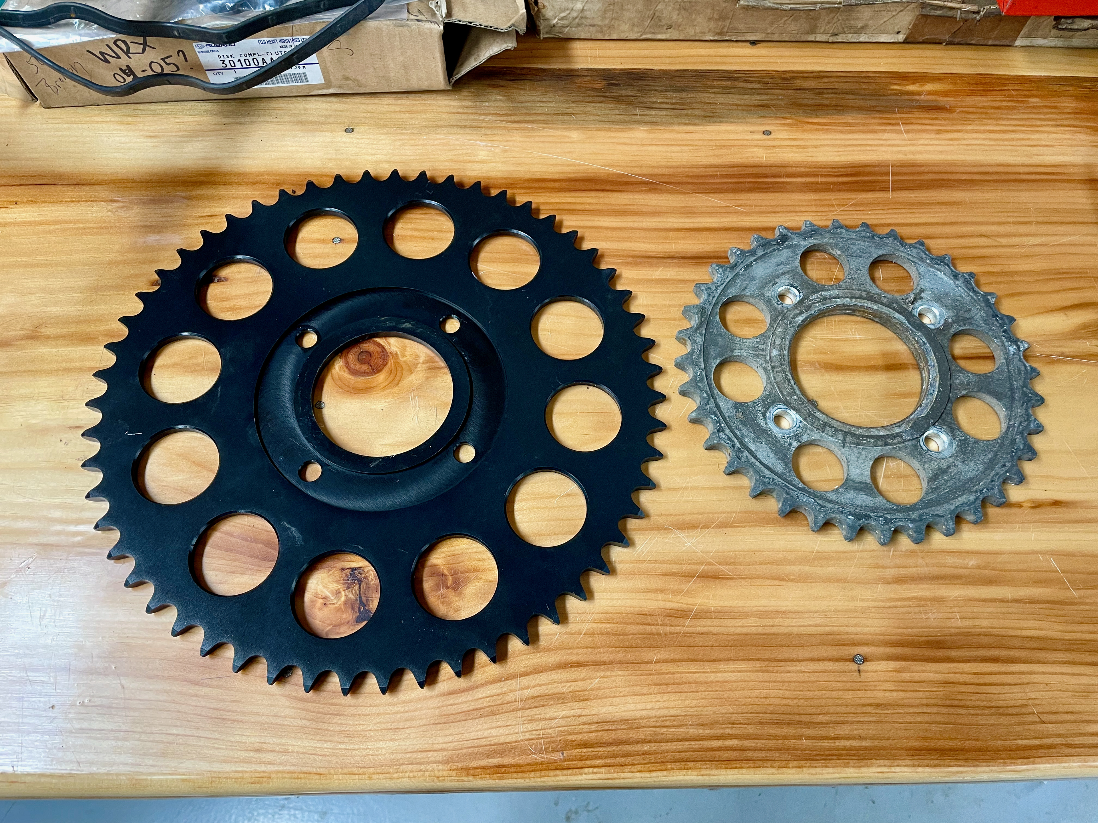
The finished sprocket (left) back from the machine shop next to the original one (right).
To achieve a lighter weight and remain compatibility with the driving sprocket, I designed the rear sprocket to be compatible with a smaller size chain. As a result, it was made 2.6mm thinner than the original sprocket, rendering the original spacer unusable. To resolve this issue, I machined a new spacer using a large steel washer.
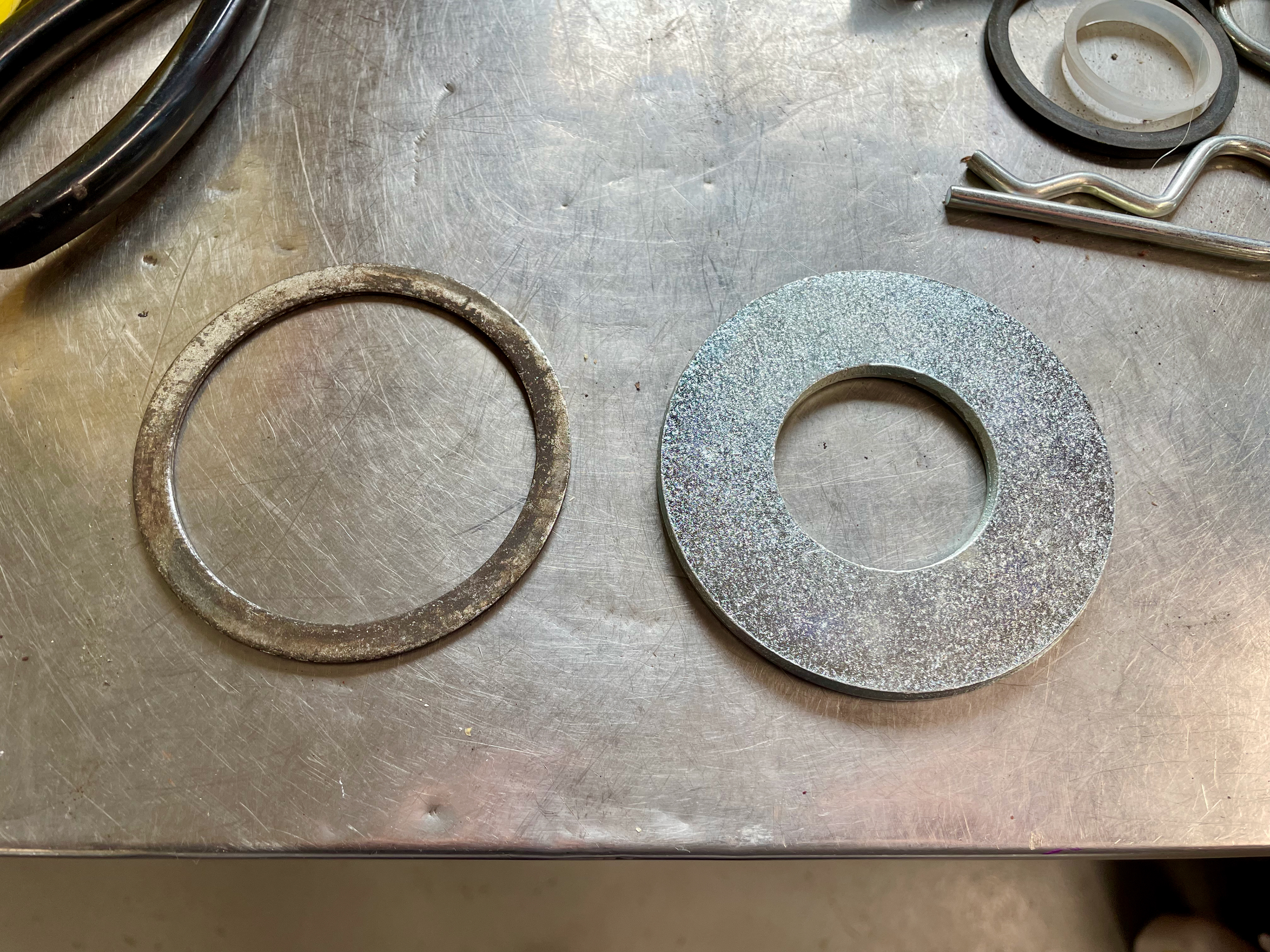
The original 2mm spacer next to the washer to be machined to size.
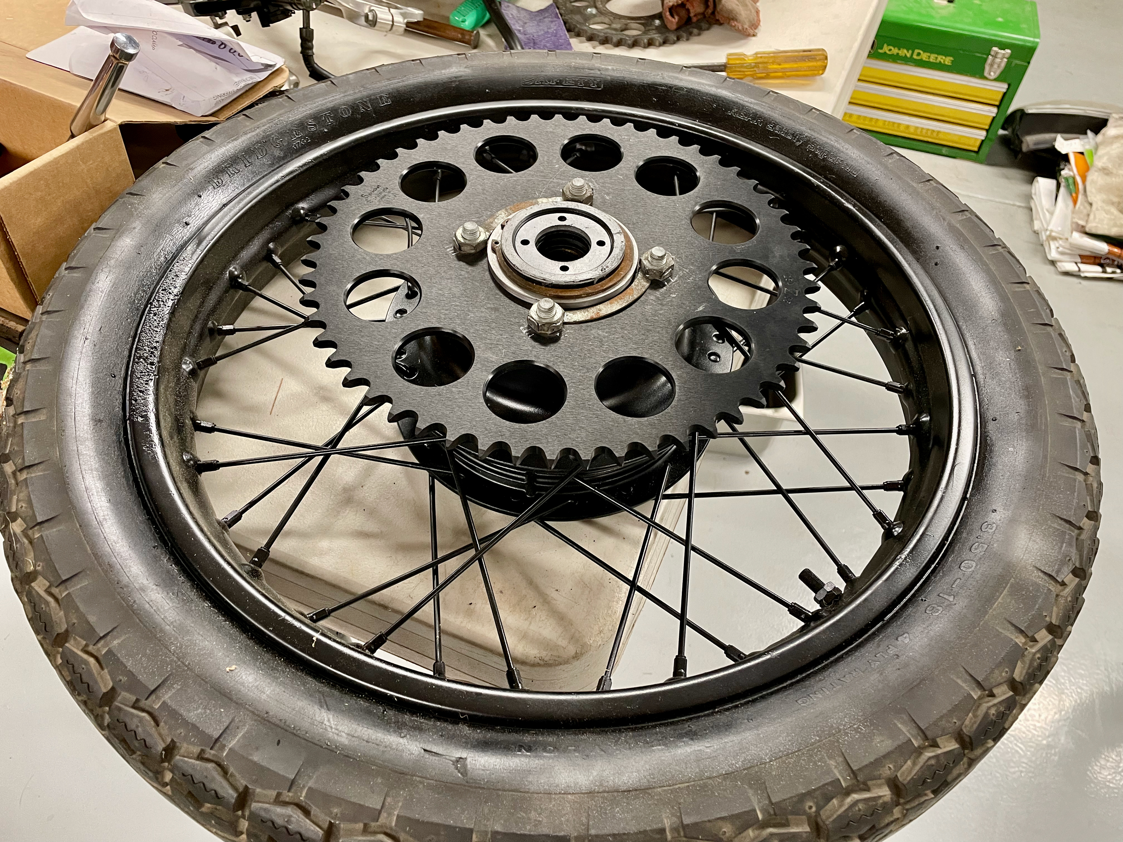
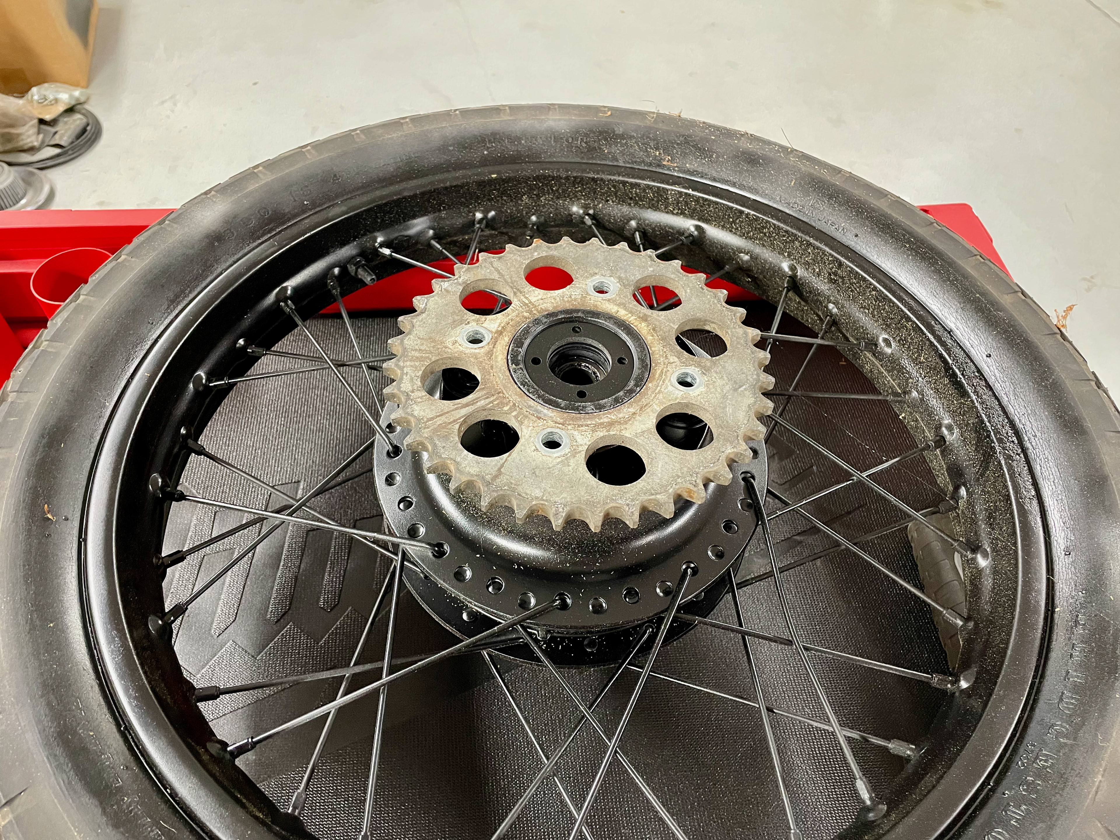
The new sprocket successfully fixed to the rear wheel. The machined spacer is shown in between the sprocket and retaining ring.
The next component to create was the motor mount. Carefully measuring key dimensions, I was able to cad up a simple frame to use as a guide (The actual frame will later be 3D scanned, imported to SolidWorks, and simulated under load when I have access to a 3D scanner). I chose 5 of the original engine mounts to use as mounting points for the new e motor. I designed the plate to flow naturally around the mounting holes and motor. A simulation was run using peak forces from the motor spec sheet to de-risk any significant deformation. With the part displacing only 0.006 mm in the weakest location with no areas exceeding the steel's yield strength, manufacturing of the part was continued. Using 1/4" stock, the part was cut with a CNC plasma cutter.
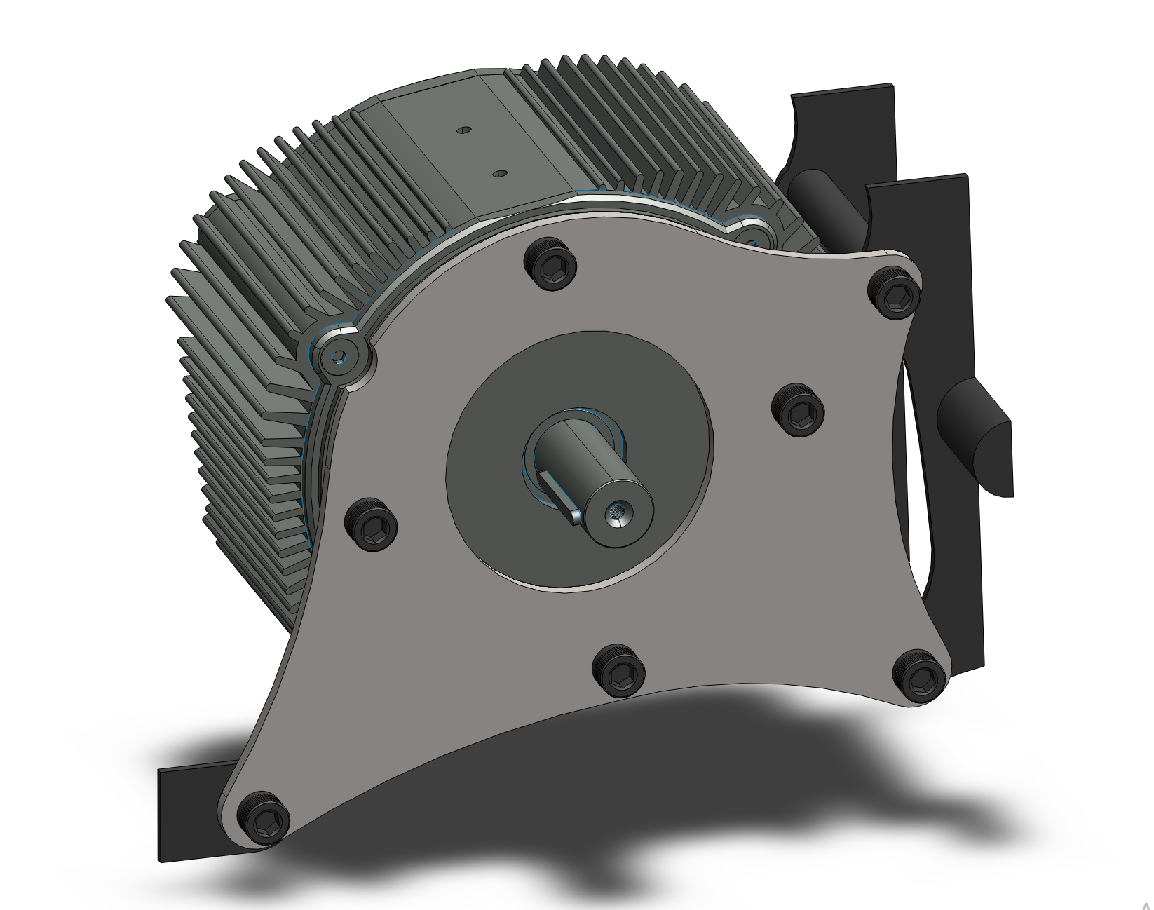
SolidWorks Assembly of the Motor Mounting Plate
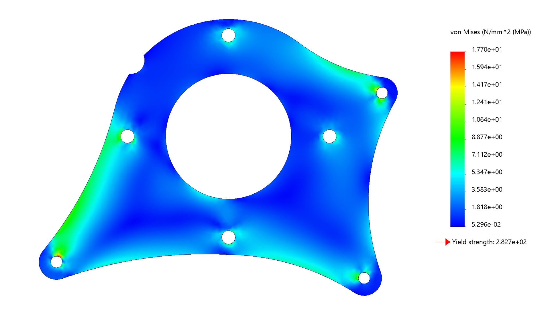
Stress Simulation
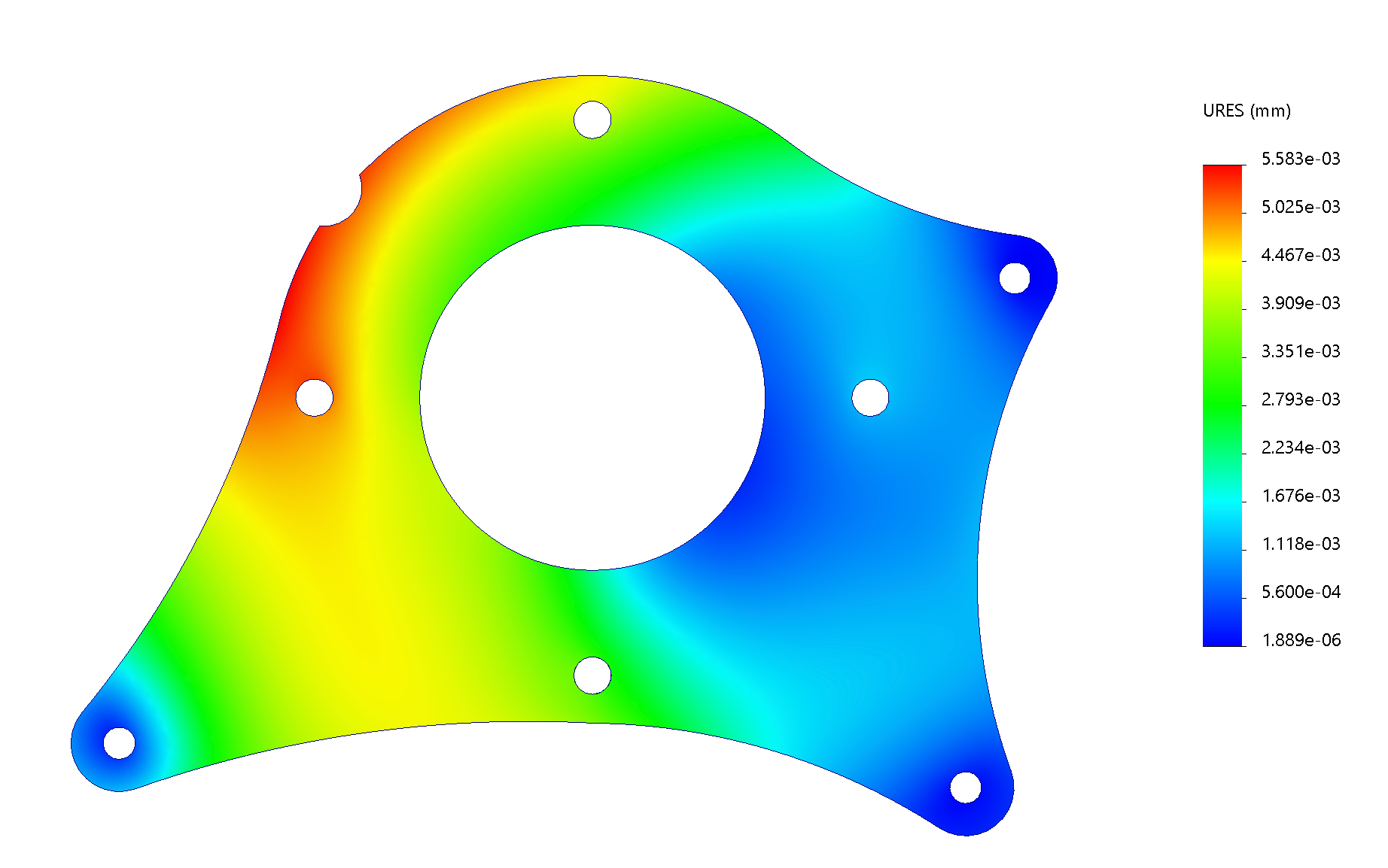
Displacement Simulation
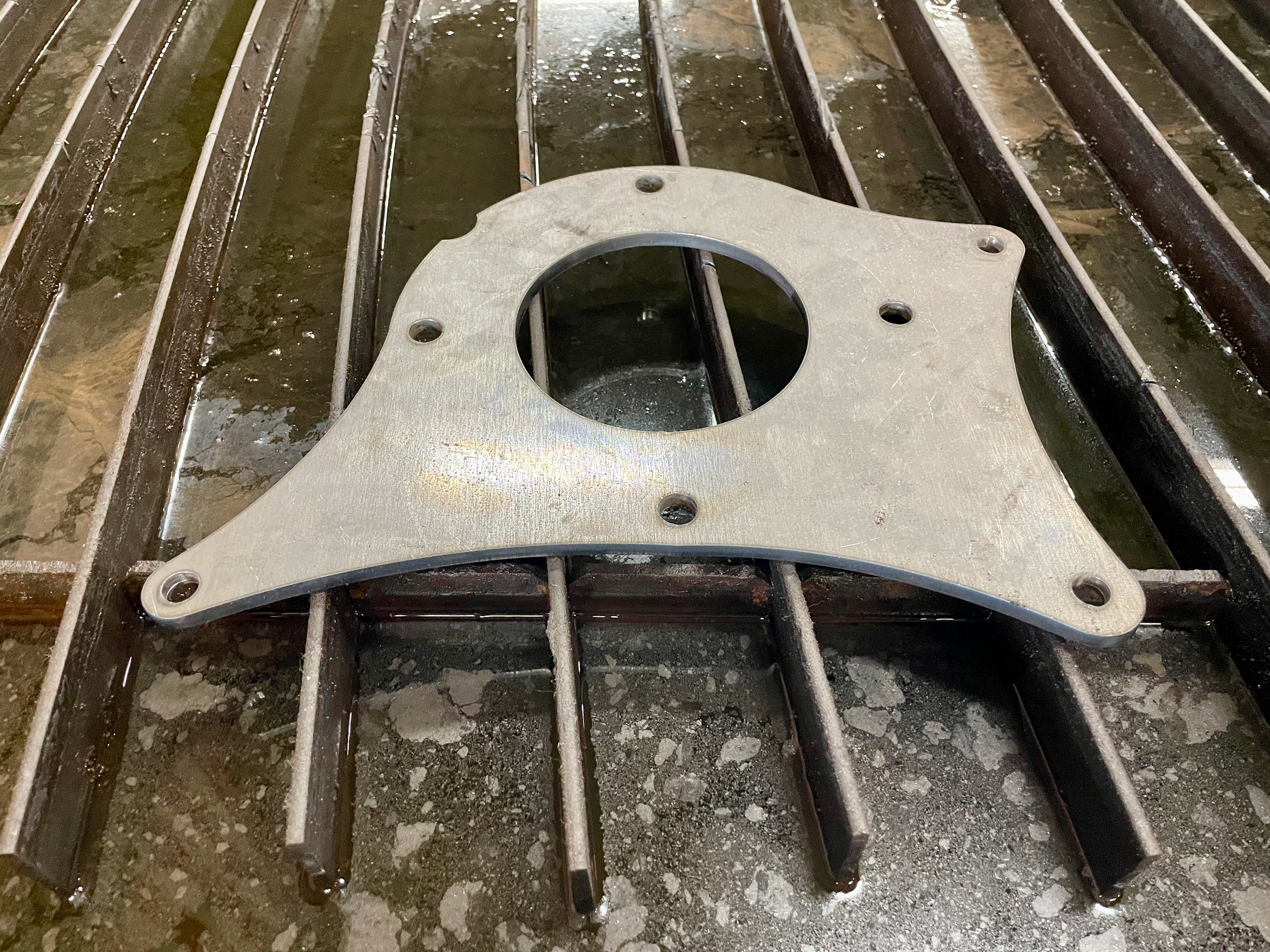
The Finished Part on the Plasma Cutter Bed
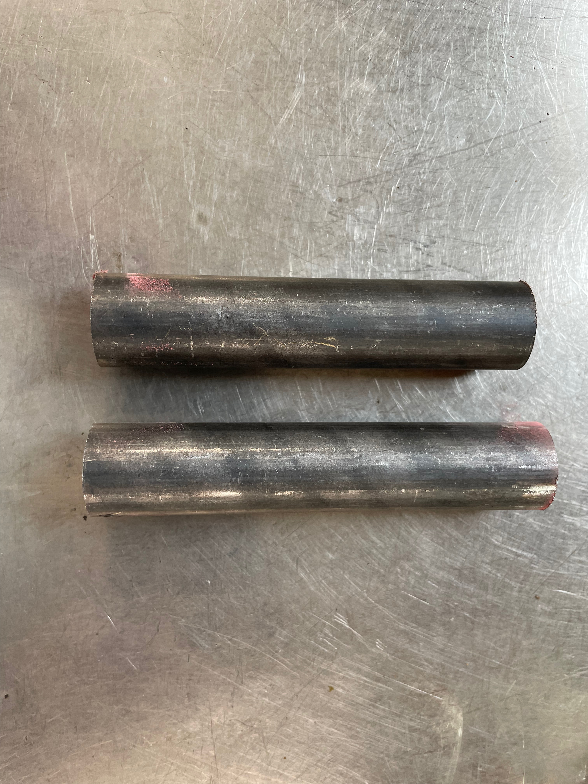
Metal Spacers were used to bridge the two rear mounting holes and provide extra strength
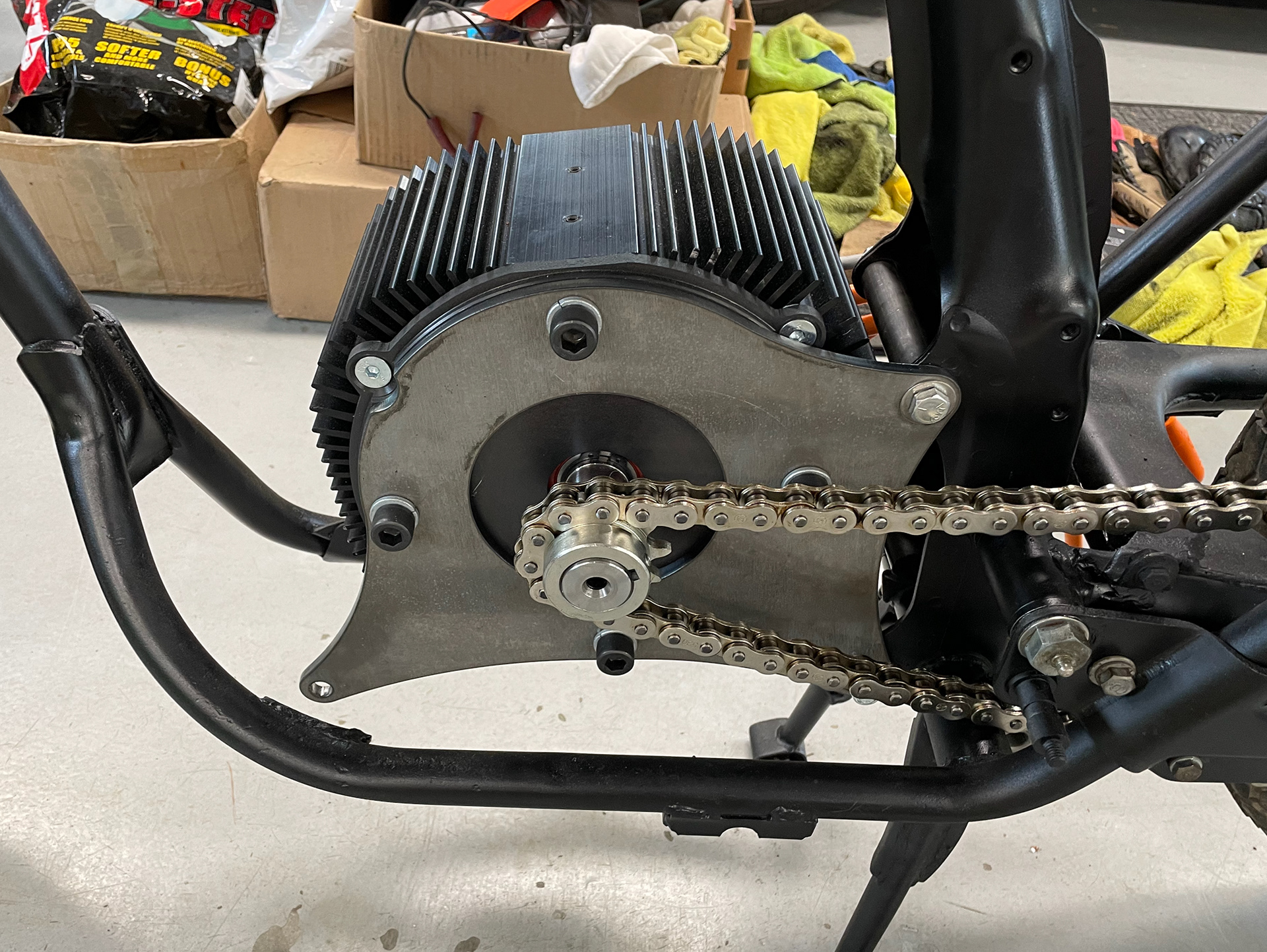
The motor end uses a 11 tooth sprocket
Next step was the motor controller. I chose the rear cavity of the frame as the mounting point for its adequate space and airflow. The controller is mounted using a carbon fiber 3D printed adapter I designed that clamps down on the frame's tubing.
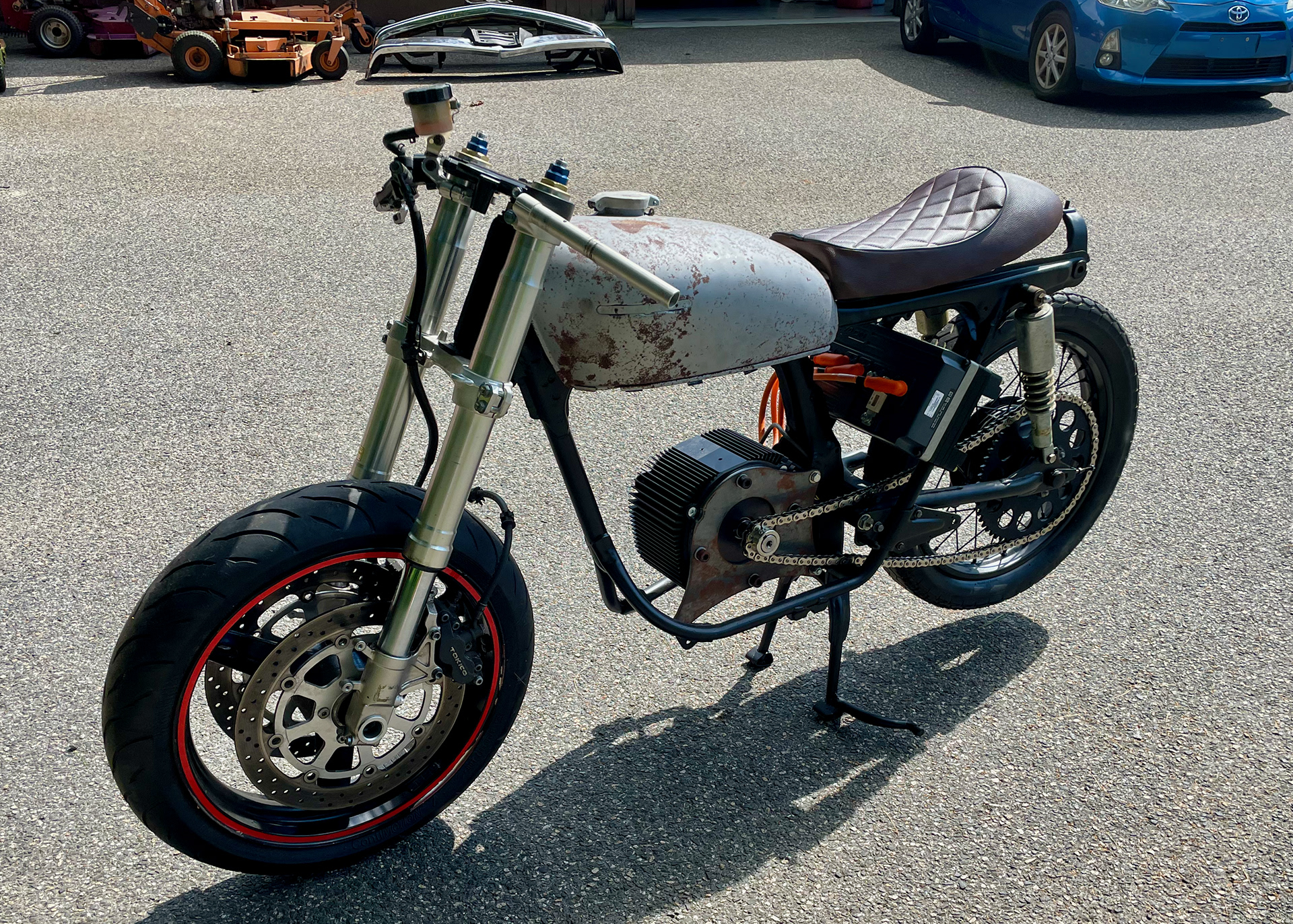
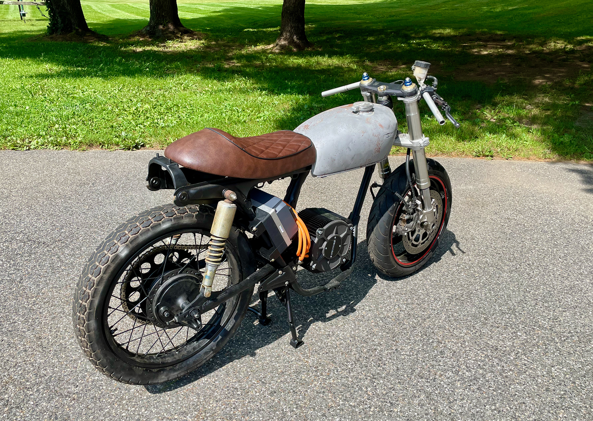
Complete with the motor controller the bike is starting to come together!